
Measuring Accumulated Charge on I-Series Products
How I-series electrometers sum charge across integrations, with dead-time correction, Diagnostic plots, and ASCII command examples.
Charge Measurement Limits
The maximum charge that can be accumulated in a single integration on an I-series electrometer such as the I400, IC101, I404, or I3200 is limited by the integrator feedback capacitor Cfb and the maximum conversion voltage VADC_max of the ADC that measures the integrator output:
Qmax = Cfb × VADC_max
VADC_max is 10.0 V for Pyramid integrator products, and the overrange flag is set at 9.8 V. The nominal 10 pF feedback setting of the I400 can therefore measure up to about 10e-12 × 9.8 = 98 pC before overrange. The actual value depends on the exact capacitor.
A larger charge can be measured on a larger feedback capacitor, but at the cost of reduced sensitivity, and there is still a limit. The same charge-integrator topology applies across the charge measurement family, including denser modern peers such as the I128, I6400, and IX256. For F-series vs I-series topology, see Choosing F or I Devices for Current Measurement.
Charge Accumulation Over Multiple Integrations
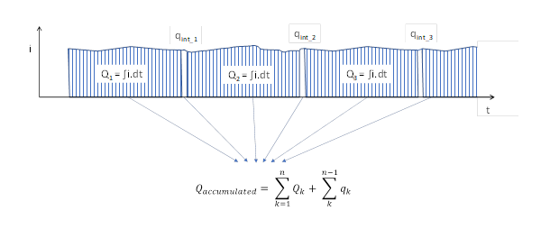
The single-integration limit is overcome by summing readings from multiple integrations. The electrometer can do this internally, and there is then no practical limit to the charge that can be measured. There is a small dead time between integrations while the integrator resets, which must be taken into account. An interpolation (estimation) calculation computes the missed charge based on the prior integration and adds it to the total. If the integration period is 5 msec or more, the amount of correction is very small.
Using Charge Accumulation Mode
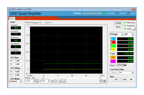
The effect of turning on accumulation mode can be seen directly in PTC Diagnostic graphics. The screenshots below show charge against time for an I400 measuring a photodiode on channel three (classic DiagnosticG1 UI; current PTC DiagnosticG2 software provides equivalent plots).
Charge Accumulation Off
Charge Accumulation On
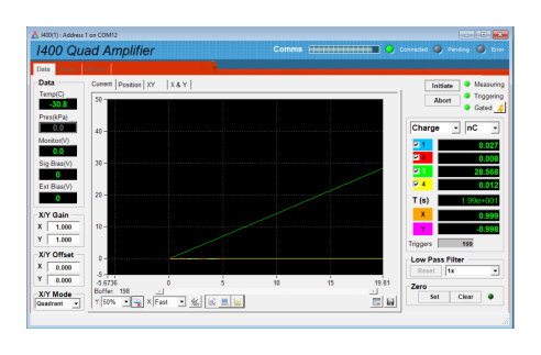
With accumulation on and estimated correction of missed charge, channel three climbs continuously across integrations.
ASCII Command Interface
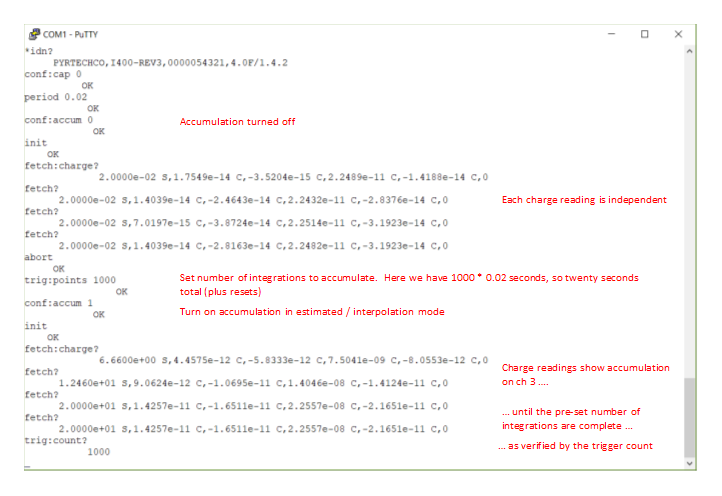
The mode is also available via the ASCII command interface. The example I400 terminal session above shows charge measurements first without accumulation, then with accumulation turned on for a specified number of integrations (trig:points with conf:accum 1 in estimated / interpolation mode). Watch progress with repeated fetch? and trig:count? queries. When accumulation is complete, the trigger count stops increasing and the values returned by fetch are fixed.
Do not use the read? command for charge accumulation: it forces an initiate on each use and resets the accumulation.
For calibration of I-series charge paths, see Calibration of Current and Charge Measuring Devices. Cabling is covered under Accessories. Contact us for application help.