
Cooling Water Requirements for Magnet Coils
Closed-loop cooling, water chemistry, and velocity limits for Pyramid hollow-conductor scan magnet coils such as the D2-650.
Scan magnets that deflect high-rigidity ion beams and change field quickly dump many kilowatts into their coils at high excitation. Pyramid coils use hollow OFHC copper so coolant flows in the conductor core and removes heat efficiently. Pair this note with the D2-650-IE scan magnet system and the broader magnetics line, and with dipole and quadrupole deflection when the beam-optics question sits beside the cooling plant.
Scan Magnets
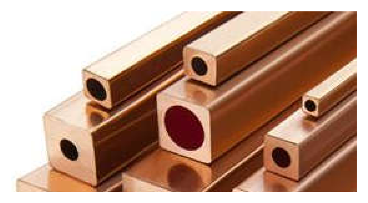
Pyramid scan magnet coils are wound with high-conductivity copper where cooling water flows in the hollow core. That geometry keeps the whole coil pack thermally manageable at peak current.
Cooling Systems
Permanent installations need a closed-circuit plant. Coolant must reach the magnet distribution manifold with enough pressure head for the required flow so the magnet stays thermally stable at maximum excitation. The loop also needs heat-removal capacity for the peak load and water chemistry that will not degrade the circuit over years of operation.
Water Chemistry
Wetted copper is unavoidable. Corrosion and deposition management has no single best practice for every site. Duffeau et al. [1] cover stator water chemistry that also applies to electromagnet coils; Zickler [2] and Dortwegt [3] give additional magnet and accelerator context. Copper oxides form over time. Depending on pH and dissolved-oxygen strategy, you can emphasize minimizing deposition or minimizing release of deposits that later clog a restriction. Reference [1] walks through the options.
When air cannot be excluded, a convenient chemistry runs deliberately high dissolved oxygen (> 2 ppm) with open air interfaces and alkaline pH between 7.5 and 9. Oxides deposit on copper surfaces, then tend to stabilize as a protective coating and stay put rather than circulate. Maintain pH with alkali such as sodium hydroxide, and keep oxygen up so those layers are not eroded.
Low-oxygen chemistry instead minimizes oxide formation, but is harder to keep. See [1] for details.
If you use biocides, check compatibility with circuit materials and pH. Treat the working fluid like an automotive coolant: maintain or change it on a schedule.
Scan magnets do not need particularly low conductivity to stand off electrical potential. Low conductivity may still result from the chosen chemistry, and conductivity remains a useful coolant-condition metric.
Wetted Materials
Copper and brass with plastic hose work together. Copper and stainless steel with plastic hose also work. Do not put brass and stainless steel in close proximity in the same circuit (galvanic corrosion risk). On the Pyramid D2-650-IE system the wetted surfaces are mostly copper and polyethylene, with small brass areas. Combined wetted area for both magnets:
| Material | Role | Area |
|---|---|---|
| OFHC copper | Hollow conductor coils | 2.98 m² |
| Brass | Coil terminations and fittings | 0.04 m² |
| Polyethylene | Connecting hoses | 0.35 m² |
Industry guidance [4] covers stainless steel in contact with other metals; [5] lists mutual galvanic potentials. Avoid large galvanic pairs in one water circuit.
Inspection and Preventative Maintenance
Years of continuous operation will move some solids around the loop. Monitoring, filtration, and maintenance methods appear in [1]. Routine hose and joint inspection, plus logged pressure drop, conductivity, and pH, supports planned replacement. Cast fittings such as valves usually age faster than machined or extruded parts because of roughness and porosity.
Magnet coils are the hardest parts to replace. Narrow bore makes them more prone to blockage, which reduces cooling efficiency, raises coil temperature at high DC current, and increases resistance (copper’s positive temperature coefficient). Include cooling-efficiency checks in machine QA. If you can measure pressure drop or flow rate, log them for early signs of reduced flow.
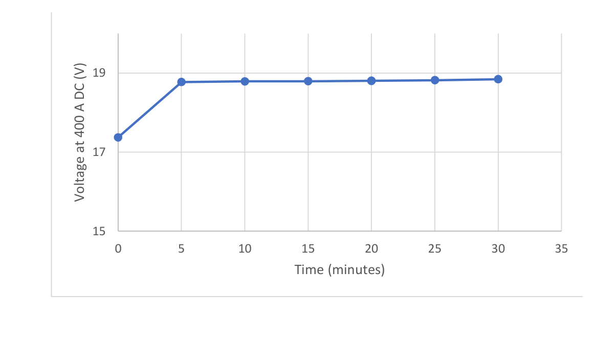
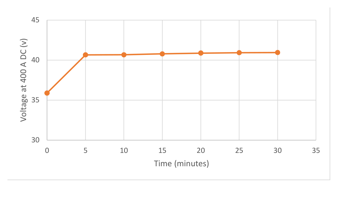
The scan magnet power supply also helps: it reports and . For the IECO MPS400-350-PY supply used with the D2-650 system, multiply readback voltages by 50 to recover actual values. At fixed known current with controlled inlet pressure and temperature, inductance is not being driven, so monitored voltage tracks ohmic resistance. At high current the coils warm to equilibrium. Excess heating from blockage raises resistance further; extreme blockage drives temperature until thermal switches interlock the supply. Logging how voltage rises with time at high current reveals cooling degradation. The test is most sensitive at high current.
When D2-650 coils are new, equilibrium voltage is reached in about five minutes at the maximum DC rating of 400 A, as in the plots below. An equivalent test for D2-640R scan magnets should use no more than 360 A.
If the cooling bore were enlarging from copper erosion, you would first see reduced pressure drop and later higher resistance as copper cross-section shrinks. That path is unlikely over system life and far less common than oxide blockages.
Water Velocity
Keep coolant velocity under 3 m s⁻¹ everywhere to limit erosion and transport of deposits toward choke points. The D2-650 magnet set specifies 12 litres per minute total flow. The minimum pipe internal diameter (cm) that keeps velocity at 3 m s⁻¹ is:
with cm s⁻¹ and cm³ s⁻¹ (). Prefer a larger diameter so speed stays well below the limit.
Coil bore is relatively small, but parallel circuits cut velocity and pressure drop across the packs. Example: the D2-650 slow-axis magnet splits flow into parallel circuits (four per coil pack). Recommended flow L min⁻¹ cm³ s⁻¹ with conductor bore cm gives:
Further Information
Browse magnetics and the D2-650-IE product page for scan hardware. Related notes: dipole and quadrupole deflection and medical proton beam parameters. Contact us or Support if you need help sizing a cooling plant for a Pyramid magnet system.
References
- François Duffeau et al., Guide on Stator Water Chemistry Management (April 2010). Guide text (and other hosts).
- Th. Zickler, “Basic design and engineering of normal-conducting, iron-dominated electromagnets” (section 4.42), CERN magnet design lectures. CDS PDF.
- R. Dortwegt, “Low-conductivity water systems for accelerators,” Proceedings of the 2003 Particle Accelerator Conference. JACoW PDF.
- The European Stainless Steel Development Association, “Stainless Steel in Contact with Other Metallic Materials,” Materials and Applications Series, vol. 10. Euro Inox PDF.
- Zyology Ltd., “Galvanic Corrosion Chart.” Anodic index PDF.