
Connecting Pyramid Products to Customer Software Using IG2/EPICS
Use Pyramid IG2 as an EPICS Channel Access bridge to control and read back devices from custom software.
Why IG2 and EPICS
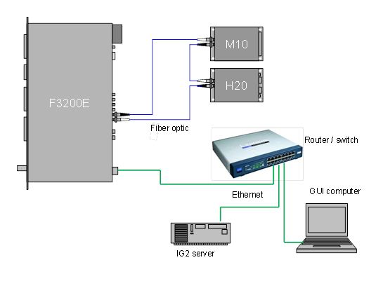
Users who want to connect Pyramid devices to their own software should use the IG2 service. It is available for Windows PCs and, on request, for selected Linux distributions. IG2 bridges the device to the EPICS service. EPICS clients are widely available in C++, C#, LabVIEW, Python, and other languages (EPICS extensions).
The interface is Ethernet. Products without their own Ethernet port connect through a fiber optic loop controller such as the A500, A360, or A560. Devices such as the F460, F3200E, C400, and I128 can also act as loop controllers. The figure shows an example where an F3200E, an M10, and an H20 all connect via EPICS.
Any EPICS client that talks to IG2 must share the same network broadcast domain. The IG2 server can run on the GUI computer or on a separate server. Related cable guidance is in Fiber Optic Cable for Pyramid Products. For electrometer and current-measurement device choice, see Choosing F or I Devices for Current Measurement.
Channel Access Server
IG2 includes an optional Channel Access Server (CAS), or Portable Server, that implements EPICS Channel Access. EPICS clients can then read back and control IG2 I/O points as Process Variables (PVs).
IG2 keeps a database of named I/O points (channels) in its configuration file (default system.xml). Each channel has a type and direction, and maps one-to-one to an EPICS PV. That channel list is the full set of PVs IG2 exposes.
Enable the CAS by adding an <epicscas> node under the <interpreter> section (typically inside the virtual devices / <devices> area):
<interpreter>
  <devices>
    <epicscas type="epicscas" name="epics_server"/>
  </devices>
</interpreter>
Running IG2
IG2 is a console application. Pass the path to the XML configuration file as the first argument:
ig2-2.0.2 c:\config\mysystem.xmlThe path is optional. If omitted, IG2 loads system.xml from the application directory.
System Configuration and Channels
system.xml lists the hardware IG2 manages. The set of supported device types and wires is updated regularly. Within each device instance you define channels that map to a wire for control and readback.
The example below configures an M10 that controls a power supply for beamline element XQ7. Channel names are arbitrary but must be unique and must not include spaces. Wire names encode data type and direction in the prefix.
<board type="M10" name="XQ7_ctrl" address="7">
  <channels>
    <channel name="c_XQ7_current_ctrl" wire="analog_out_1" limitLow="-10" limitHigh="10" />
    <channel name="r_XQ7_current_ctrl" wire="analog_in_1" scaleB="2" scaleC="1" />
    <channel name="r_XQ7_thermalok" wire="digital_in_1" />
    <channel name="c_XQ7_remote" wire="digital_out_2" />
  </channels>
</board>
Wire Types
| Wire name | Data type | User access |
|---|---|---|
analog_in_xxx |
Double (64-bit) | Read only |
analog_out_xxx |
Double (64-bit) | Read/Write |
int_in_xxx |
Integer (32-bit) | Read only |
int_out_xxx |
Integer (32-bit) | Read/Write |
digital_in_xxx |
Integer (32-bit); 0 = false, non-zero = true | Read |
digital_out_xxx |
Integer (32-bit); 0 = false, non-zero = true | Read/Write |
variant_in_xxx |
Array of doubles (64-bit) | Read |
variant_out_xxx |
Array of doubles (64-bit) | Read/Write |
analog[n]_in_xxx |
Array of doubles (64-bit), length n | Read |
analog[n]_out_xxx |
Array of doubles (64-bit), length n | Read/Write |
The xxx suffix is device-specific.
Scale Factors and Limits
Analog channels can include optional scale factors that convert between user units and device units (scaleB, scaleC):
y = Bx + Cwhere y is user units and x is device units. If omitted, scaleB = 1 and scaleC = 0.
Analog output channels can also set limitLow and limitHigh in user units. Those limits are independent of the device’s physical limits.
Buffering and Monitors
EPICS buffering is limited. High-rate bursts can drop data before it reaches clients. Enable sample buffering on a channel with optional aMax (maximum buffered acquisition size; default 0 = unbuffered):
<channel name="bufferedchn" wire="analog_in_1" aMax="50" />Set aMax high enough for the device’s buffered acquisition (or lower if client throughput and channel count allow).
By default, a monitor event can fire even when the value is unchanged. To emit monitors only on change (digital, integer, or analog channels):
<channel name="digitalchn" wire="digital_in_1" monitorOnlyChange="true" />Real-Time Processor Config
Some products accept an XML file that defines calculations and fault conditions on the real-time processor. Point system.xml at that file with rtpfile:
<loopcontroller type="A560" name="A560_1" ip="192.168.100.123" rtpfile="RTConfig.xml">For full detail, see the latest ig2_manual.docx user manual.