
Choosing F or I Devices for Current Measurement
Learn when to choose Pyramid F-type or I-type devices for low current and charge measurement: noise, bandwidth, deadtime, and pulsed signals.
Measuring Small Currents
Pyramid electrometers include two types of low current measurement device; “F” type like the F100, F460, F3200E, and FX4, and “I” type like the IC101, I404, I400, I3200, and high-channel I6400 and IX256. In order to digitize the measurement with an analog to digital converter (ADC) it is first converted to a voltage. The way this is achieved is what distinguishes the two types. The best type to choose depends on the user’s application. In simple summary, an F type device is preferred if time-resolution, contiguous data and higher current capability are important, while an I type device is preferred where very small currents must be measured, where charge is the actual measurement of interest, or where a large number of channels are needed.
F Devices
F type devices use the I-V converter circuit topology, also known as a transimpedance amplifier. The input current passes through a resistor to develop a voltage according to Ohms law. An operational amplifier is used so that the device does not cause the voltage on the input to rise from zero, thus ensuring that the measurement device is not perturbed, and that no signal is lost to ground through stray resistances.
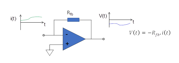
The voltage output tracks the current input continuously. Very high frequencies are attenuated due to the bandwidth of the operational amplifier circuit and stray capacitances in the sensor, cables and electronics. Further low-pass filtering is necessary to ensure that the sampling rate of the following ADC is much higher than the highest frequency in the analog voltage signal. A factor of five at least is typical, so for example a digitization rate of 250 kilosamples per second requires a filter with DC to 50 kHz bandwidth.
I Devices
I type devices use an alternative converter circuit with a capacitor as the feedback element. The output is now the voltage across the capacitor, which reflects the charge q accumulated according to V = q/C. An I device is thus a charge integrator, and the relationship to the input current depends on the integration time t according to q = it. Since i is generally a function of time, i(t), a better expression is q = ∫i(t)·dt. The use of a capacitor to integrate the current signal averages noise and allows very small currents to be measured.
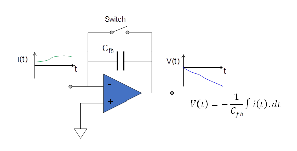
The integration time is set by the opening and closing of a reset switch. Each integration yields a charge measurement which can also be expressed as average current during the integration because the time is known accurately. The maximum time is limited by the allowable voltage range on the output, limited in practice by the range of the ADC. The closing and opening of the switch resets the integrator. During the reset cycle, typically 50 microseconds, the signal is not measured so there is some deadtime. At integration times of 10 milliseconds or more this has negligible effect on the accumulated charge reading, but at short integration times it must be considered.
The I128 I device eliminates reset deadtime by having two integrator circuits per input channel and switching quickly from one to the other.
Selecting the Appropriate Device
For many applications either F or I type will perform well, and selection can be made based on features such as number of channels, additional inputs and outputs, size and price. For other cases the nature of the signals to be measured and the results required will determine the selection. Consider some current signals to be measured.
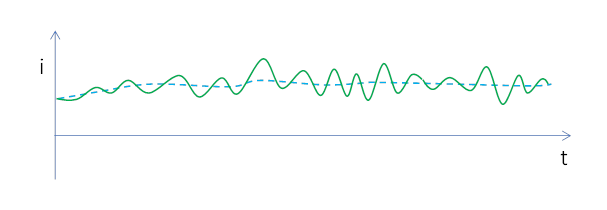
The first example is the most typical. The current varies relatively slowly with time, but there are noise fluctuations superimposed. The value of interest is the moving average (dashed line); we want to filter out the fast noise fluctuations. Both F and I devices are suitable, with F devices preferred if the average signal level is high (100’s of µA or more) and I devices preferred if the signal level is low (below 1 nA).
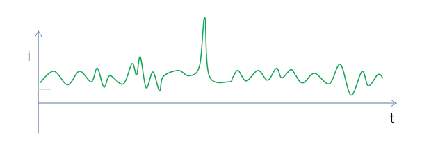
In the second example there is a fast transient event that we wish to record rising above the noise fluctuations. The F device is the appropriate choice. It does not have any reset deadtime which could mask the event, and it is possible to sample the data at a relatively high speed, provided that the current is high enough to avoid the need for much averaging.
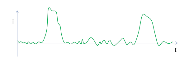
In the third example there are pulses of current separated by intervals where there is only noise. Most often the total charge in each pulse is required. An I device triggered just before the pulse arrives is ideal for this measurement. The pulse can be very short, provided that the peak instantaneous current does not exceed about 100 µA. If the time profile of the pulses is required, then an F device is the better choice, provided the pulse duration is around 20 µsec or greater so that there are enough samples covering the pulse.
Noise Levels
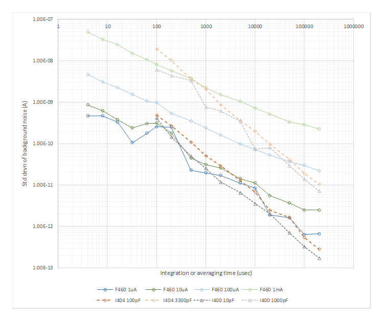
The first plot shows the standard deviation of repeat readings of the background signal for an F device (F460 on each of its four current ranges) and two types of I device (I404 and I400 on each of their two feedback capacitor settings), with the input connected to a small ionization chamber via coaxial cable. Increasing averaging (F device) or integration time (I device) reduces the noise level because higher frequencies are filtered out.
Note that the I devices can reach lower noise level at long integration times and that the F device can sample much faster by using short averaging times. Over much of the range the F and I devices offer similar noise performance.
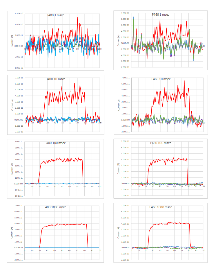
The second figure compares the ability of the F460 and I400 to detect a small current from a miniature ionization chamber connected to one of the inputs. Each device was set to its most sensitive range, and the averaging time or integration time was increased from 1 msec up to 1 second. During the data acquisition a small radioisotope source was placed next to the ionization chamber to provide a measured current of about 40 pA.
At short averages or integrations, the performance is very similar. Long integrations show the better noise floor of the I device.
Frequency Response
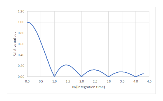
The I devices perform block averaging of the current; this is equivalent to the use of a rectangular FIR filter. The resulting frequency response has zeroes at multiples of the integration time.
While this response does mean that some higher frequency noise can affect the measurement, it provides the great benefit of being able to completely suppress some typical noise sources. For example, 50 or 60 Hz line is prevalent in most environments. If an integration time of 20 msec is used, then the first zero at N=1 is 1/0.02, or 50 Hz, so 50 Hz line will not appear in the measurement. The equivalent integration time for 60 Hz is 16.67 msec, and 100 msec serves to eliminate both frequencies.
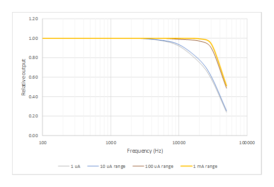
The frequency response of an F device reflects the low pass analog filter that is used to prevent aliasing of high frequency noise into the measurement. More filtering is used on the sensitive ranges to ensure stability. The following graph shows how the response starts to fall away at high frequencies for two of the current ranges of the F460. The -3dB point where the response at the frequency is down to 70.7 % of the DC value is 22 kHz for the 1 µA and 10 µA ranges, 38 kHz for the 100 µA range and 40 kHz for the 1 mA range.
The F device averaging performs block averages of the ADC values, and thus has the same type of frequency response as the I devices. At larger averaging times this dominates, and the same method can be used to suppress line frequency noise.
Summary
- F devices measure current; I devices measure charge. Average current and charge are simply related if the integration time for the charge is known.
- I devices have better low current performance (about 500 pA and below).
- F devices can measure higher currents (above 100 µA).
- I devices have lower noise at long integration times (20 msec or longer).
- I and F have similar noise performance at medium and short integration or averaging times.
- F devices have no deadtime.
- I devices are available with larger channel counts (I6400, I128, IX256).
- I devices are well-matched to integrating pulsed signals.
- F series can sample the signal faster, so are preferred if time resolution is important.
- See also Calibration of Current and Charge Measuring Devices for built-in sources, external checks, and HV calibration.